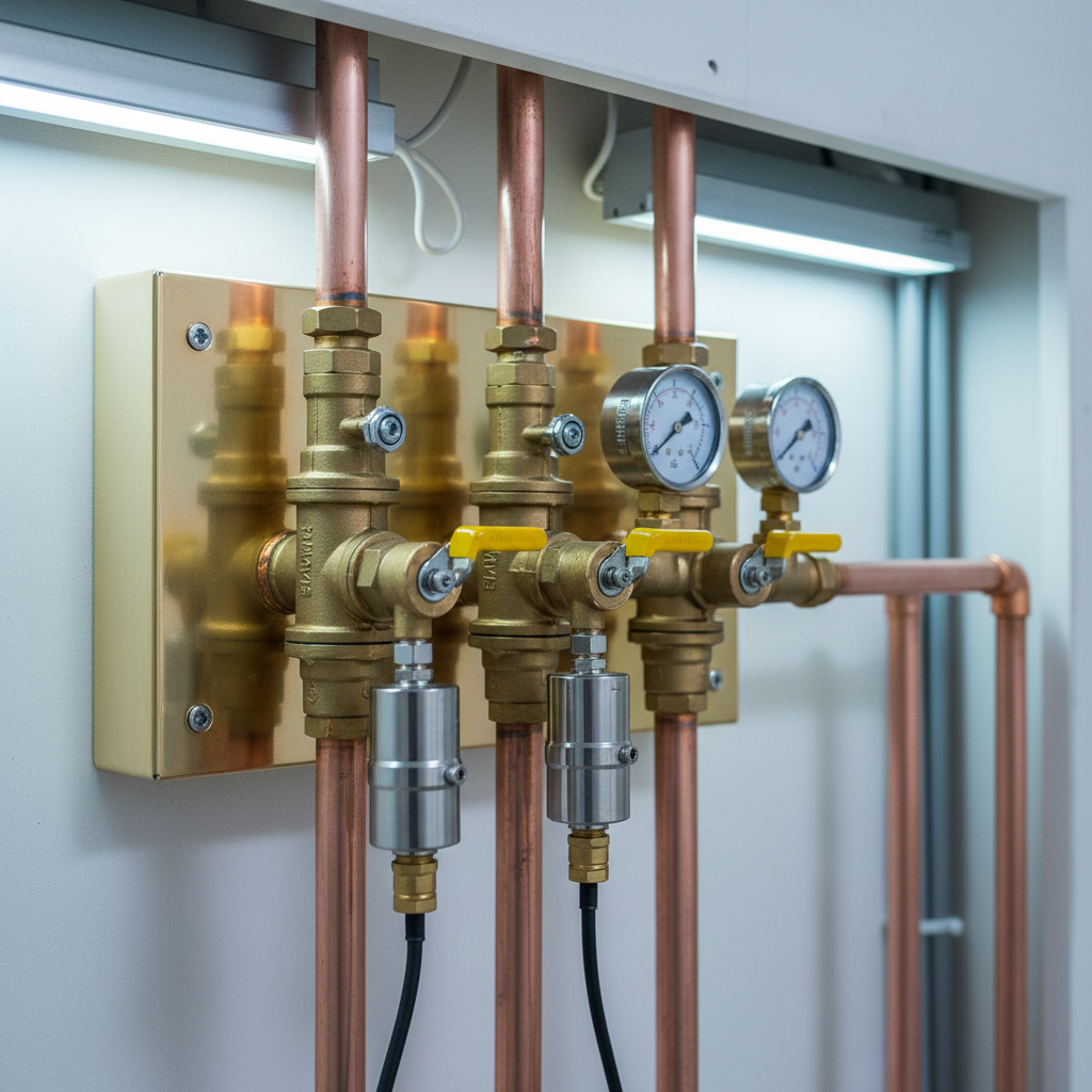
During an emergency drill in an intensive care unit, the charge nurse pulls the ring on a recessed emergency shutoff box and slams the three-piece ball valve handle ninety degrees to isolate oxygen to the wing. The physical pipeline downstream of that box drops to zero pounds per square inch as nurses bleed the terminal outlets at the headwalls. Yet thirty feet down the corridor at the nurse's station, the digital area alarm panel continues to display a steady green 52 psig, silent and unbothered.
When an ASSE 6030 verifier opens the wall access panel above that assembly to investigate, the root cause takes about three seconds to spot. During a previous renovation, a mechanical contractor brazed the pressure transducer sensing tee onto the supply riser side of the valve rather than the downstream branch feeding the patient rooms. Because the main riser remained pressurized from the bulk liquid oxygen source outside, the transducer read main line pressure while the patients downstream had no gas at all.
Getting zone valve box sensor placement NFPA 99 rules right on the drawing board and in the wall cavity prevents this exact failure mode. Area alarm sensors do not exist to monitor the main hospital riser. They exist to tell clinical staff in a specific care area what is happening inside the exact pipe feeding their patient beds after the local isolation point.
The Core Rule for Zone Valve Box Sensor Placement in NFPA 99
The National Fire Protection Association leaves zero ambiguity about where pressure transducers, gauges, and demand switches belong relative to a local shutoff valve. Under NFPA 99 (Health Care Facilities Code), Section 5.1.9.3.4, sensors for area alarms must be placed on the patient or use side of each individual zone valve box. Look closely at the code organization in Chapter 5 and you will see a strict division between how general vital life support areas (Category 1 and Category 2 spaces) are monitored compared to anesthetizing locations.
Every area alarm panel monitors the high and low pipeline pressures or vacuum levels for a specific clinical boundary. For positive pressure medical gases such as oxygen, medical air, nitrous oxide, carbon dioxide, and heliox, the panel triggers an audible and visual warning when line pressure increases or decreases by 20 percent from normal operating pressure (typically triggering below 40 psig or above 60 psig on a standard 50-55 psig system, or +/- 20 percent on a 160-185 psig nitrogen or instrument air line). For medical-surgical vacuum and waste anesthetic gas disposal (WAGD), the sensor triggers an alarm when vacuum drops below 12 inches of gauge mercury (inHg).
If you place that sensing port upstream of the zone valve, on the source side, closing the zone valve traps line pressure on the upstream side while isolating the patient outlets downstream. The sensor stays satisfied because the upstream main riser is still pressurized. Consequently, closing the valve during a fire or a catastrophic outlet rupture produces no alarm at the nurse's station. Worse, if someone accidentally closes a zone valve or fails to reopen it fully after maintenance, the clinical team has no electronic warning that their patient outlets are starved of gas.
Why this matters for compliance: During The Joint Commission (TJC), DNV, or state Department of Health physical environment surveys, inspectors routinely cross-reference zone valve physical locations against area alarm transducer taps. An upstream sensor placement is cited as an immediate Category 1 life safety deficiency under NFPA 99 5.1.9.3.4 and requires emergency re-piping and formal recertification before patient occupancy can continue.
Anatomy of a Zone Valve Box and Its Factory Port Tap Locations
To understand why installers occasionally wire or plumb sensors onto the wrong side of the valve, you have to look at how modern zone valve boxes are manufactured and shipped. A compliant zone valve box under NFPA 99 Section 5.1.4.6 consists of a quarter-turn, full-port, three-piece brass or bronze ball valve housed inside a recessed rough-in steel or aluminum enclosure with a removable break-away or pull-ring window covering the operating handles.
When you pull a multi-gas zone valve box out of the crate from major manufacturers like BeaconMedaes, Amico, Ohio Medical, or Tri-Tech Medical, the copper Type K or Type L tube extensions pre-brazed to each side of the bronze valve body include factory-brazed brass gauge ports and transducer ports.
Mechanical Pressure Gauges vs. Electronic Alarm Sensors
Do not confuse the mechanical pressure gauge screwed directly into the valve body with the electronic area alarm transducer. NFPA 99 Section 5.1.4.6.1(3) requires every zone valve box to incorporate a readable pressure or vacuum gauge on the patient or use side of each valve. Manufacturers machine and braze a 1/8-inch NPT female brass boss on the downstream copper stub right inside the box enclosure solely for this mechanical Bourdon-tube dial gauge.
Electronic area alarm sensors, however, can be mounted in one of two configurations depending on the brand of the alarm panel and the engineer's specification:
- Local In-Wall or In-Box Mounting: The electronic pressure transducer wires into a low-voltage backbox next to the zone valve, or threads directly into a secondary 1/8-inch or 1/4-inch NPT port (often equipped with a DISS check-valve demand fitting) located on the patient-side copper stub inside the zone valve housing.
- Remote In-Panel Mounting: The sensor modules plug directly into the circuit board inside the area alarm rough-in box down the hall, and the installer runs 1/4-inch (3/8-inch OD) Type K or L copper sensing lines from the patient side of the zone valve over to the alarm box.
When a zone valve box is ordered from the factory, you must specify the flow direction: Left-to-Right (L-R) or Right-to-Left (R-L), or Up-to-Down on vertical configurations. Because the mechanical gauge port and the factory DISS sensor port are permanently silver-brazed onto one side of the ball valve at the factory, flipping a Left-to-Right box upside down in the wall to accommodate a Right-to-Left pipe routing puts the factory ports on the supply side instead of the patient side.
Even if an installer unbolts the valves and flips them inside the steel enclosure to correct the flow arrow, they sometimes forget that the remote sensing tee they brazed in the ceiling cavity above the box is still sitting on the supply riser drop. Correct medical gas installation requires tracing the physical direction of flow from the riser branch Valve all the way through the zone valve box to the terminal outlets before striking an arc with a brazing torch.
| Placement Parameter | General Vital Support Areas (ICU, NICU, ER, Med-Surg) | Anesthetizing Locations (Operating Rooms, C-Section, Procedure) |
|---|
| Governing NFPA 99 Code (2018/2021/2024) | Section 5.1.9.3.4(1) | Section 5.1.9.3.4(2) |
| Zone Valve Location | Immediately outside the vital area served, visible and accessible in the corridor | Immediately outside each individual operating or anesthetizing room |
| Required Sensor Tap Location | Patient (downstream) side of the individual zone valve box | Either patient side of individual room zone valves OR patient side of an upstream vital area zone valve grouping the OR suite (verify local edition/engineer spec) |
| Response to Closing Room Zone Valve | Immediate Low Pressure / Low Vacuum alarm on the area panel | Alarms immediately if tapped on room patient side; will NOT alarm if tapped upstream of individual OR valves without a secondary room sensor |
| Factory Gauge Position | Patient (downstream) side inside the valve box | Patient (downstream) side inside the valve box |
Critical Nuances: General Patient Care vs. Anesthetizing Locations
One of the sharpest technical distinctions in NFPA 99 involves how sensor placement rules bifurcate between general Category 1 patient care areas (like ICUs, CCUs, and recovery bays) and anesthetizing locations (Operating Rooms and Cath Labs). If you read NFPA 99 Section 5.1.9.3.4 carefully across recent code cycles, the wording splits into two distinct clauses.
For vital life support and critical care areas, the sensor must sit on the patient or use side of each individual zone valve box. One zone valve box typically controls a cluster of 8 to 16 ICU beds. One area alarm monitors that exact zone downstream of the valve. The relationship is one-to-one.
Anesthetizing locations present an architectural headache. NFPA 99 requires an individual zone valve box immediately outside the corridor door of every single operating room so staff can shut off gas to OR #3 during a surgical fire without cutting off oxygen and nitrous oxide to patients under anesthesia in OR #1, OR #2, and OR #4. If a surgical suite has twelve operating rooms, it has twelve separate zone valve boxes lining the surgical corridor.
If the code forced hospitals to install twelve separate multi-gas area alarm panels at the main surgical control desk, or to wire twelve separate transducers per gas into a massive centralized marquee panel, the nurse's station wall would be wallpapered with dozens of alarm modules. Conversely, if a designer tries to pipe twelve individual downstream sensing lines together into a common manifold for one sensor, they create a lethal cross-connection that bypasses the individual room zone valves entirely.
To solve this, NFPA 99 permits two engineered paths for anesthetizing suites:
- Individual Room Sensing with Multi-Zone Alarm Panels: The engineer specifies a modular or multiplexed area alarm panel capable of accepting isolated sensor inputs wired from the patient side of each individual OR zone valve box. When OR #3's valve is shut, the central panel specifically identifies "OR #3 Oxygen Low."
- Suite-Level Upstream Zone Valve Sensing: In several editions of NFPA 99 (specifically detailed in 5.1.9.3.4(2) and the accompanying Annex A explanatory material), sensors for anesthetizing locations are permitted to be located on the source side of the individual room zone valves, provided they are still downstream of the main branch line or main suite zone valve serving that group of anesthetizing rooms, or placed on the patient side of each individual room zone valve.
However, facility engineers and medical gas verifiers must be extremely careful here. While tapping on the source side of individual OR valves (downstream of a master suite valve) prevents having to install twelve separate alarm panels, it means closing the individual valve right outside OR #4 will not set off the corridor area alarm. Anesthesia machines inside the OR have their own internal supply pressure alarms that will shriek the instant pipeline pressure drops, which is why the NFPA technical committee historically allowed this distinction.
Even so, most modern healthcare engineering specifications and hospital standards reject suite-level upstream sensing and mandate individual downstream room sensors tied into networked digital area alarms so the central surgical desk has immediate visibility into every single room valve. At Medical Testing Solutions, we verify both the engineered design drawings and the local Authority Having Jurisdiction (AHJ) edition adoption before signing off on surgical suite layouts.
Why Installers Get Sensor Placement Wrong in the Field
Nobody walks onto a hospital construction site intending to install an area alarm transducer backwards. Yet our ASSE 6030 verifiers uncover reversed or misplaced sensors on new builds and renovations every single month. Four specific mechanical and layout traps cause almost all of these errors.
1. Reversing Box Orientation Without Moving External Sensing Tees
When a zone valve box does not use internal factory DISS sensor ports and instead relies on brazed tees above the ceiling grid, the plumber often roughs in the sensing tee on the horizontal run before the final ceiling framing is completed. If the ceiling coordination changes and the pipe routing flips from entering the left side of the box to entering the right side, the installer might flip the valves inside the box so the mechanical gauges sit on the patient side, while forgetting that the 1/4-inch sensing tee two feet up in the plenum is now sitting on the supply side.
2. Using a Common Sensing Header Across Multiple Zone Valves
We occasionally find an installer who has been told to monitor two different patient wings (each with its own zone valve box) using a single non-expandable area alarm panel. Trying to make one sensor read two zones, the installer runs a 1/4-inch copper tube from the patient side of Zone Valve A and ties it with a brass tee into the patient side of Zone Valve B, feeding a single transducer.
This is a catastrophic code violation. That 1/4-inch copper jumper acts as a bypass loop around both zone valves. When you close Zone Valve A during an emergency, gas from Zone B flows backward through the 1/4-inch sensing tube and feeds the fire or leak in Zone A. Furthermore, the alarm never triggers because Zone B keeps the shared transducer pressurized at 50 psig.
3. Tapping Downstream of an In-Line Check Valve
Sometimes an installer attempts to isolate multiple zones on a single sensor by placing inline check valves in the sensing lines. This violates NFPA 99 immediately. If a check valve is installed between the pipeline and the pressure transducer, the transducer can read a rise in pressure, but when pipeline pressure drops on the patient side of the zone valve, the check valve closes and traps 50 psig against the face of the transducer. The alarm will never register a low-pressure loss of gas.
4. Confusing Main Line Riser Sensors with Area Alarm Sensors
NFPA 99 requires the master alarm system (Section 5.1.9.2) to monitor the main supply line pressure downstream of the main shutoff valve via pressure switches or transducers. Those master alarm sensors belong on the main riser or main supply header. On small ambulatory surgery center (ASC) projects where the main line valve and the first zone valve sit within a few feet of each other in the same mechanical corridor, contractors frequently mix up the low-voltage twisted-pair wiring between the master alarm mainline transducer and the area alarm zone transducer.
Gas-Specific Sensor Placement Requirements: Positive Pressure vs. Vacuum and WAGD
Proper zone valve box sensor placement NFPA 99 compliance requires looking at every utility inside the rough-in box, not just oxygen. A typical 4-gas or 6-gas surgical or ICU zone valve assembly manages positive pressure gases alongside sub-atmospheric pipelines like medical-surgical vacuum and WAGD.
Positive Pressure Gases (Oxygen, Medical Air, Nitrous Oxide, Carbon Dioxide, Nitrogen)
All positive pressure gases must have their sensors tapped on the patient side of the valve using gas-specific, non-interchangeable fittings. Under NFPA 99 Section 5.1.8.2.3, every pressure sensing device and gauge must be equipped with a gas-specific Diameter Index Safety System (DISS) demand check fitting (or equivalent manufacturer-specific non-interchangeable demand check valve).
Why a demand check fitting? It allows a technician performing annual medical gas inspections or maintenance to unscrew the electronic transducer from the pipeline while the system remains live at 50 psig without venting oxygen into the wall cavity or shutting off gas to patients in the ICU. As soon as the transducer threads off the fitting, the internal spring-loaded check ball seats and seals the pipeline.
Medical-Surgical Vacuum and WAGD
Vacuum and WAGD lines also require sensor placement on the patient (inlet) side of the zone valve. The terminology here trips up apprentice installers because the physical flow of air inside a vacuum pipe moves in the opposite direction of a positive pressure gas.
In an oxygen line, gas flows from the bulk tank, through the riser, through the zone valve, and out to the patient terminal outlet. The "patient side" is physically downstream of the flow. In a vacuum or WAGD system, air and waste gas are pulled from the patient terminal inlet, through the zone valve box, into the main riser, and down to the vacuum pumps in the basement. Regardless of the fact that air is being sucked toward the source equipment, the "patient or use side" of a vacuum zone valve is still the branch pipe side connected to the patient rooms, not the riser side connected to the vacuum pump.
Why this matters for compliance: If a contractor taps a vacuum transducer on the pump (source) side of a vacuum zone valve, closing that zone valve isolates the patient rooms from suction while the vacuum pumps pull the riser down to a deep 22 inHg. The area alarm will display a healthy 22 inHg while doctors in the operating room have zero suction at the wall inlet. Also note that per NFPA 99 5.1.8.2.3.2, demand check fittings must NEVER be used on vacuum or WAGD gauge or sensor ports, because vacuum will suck the internal check ball closed and block the transducer from reading line drop. Instead, vacuum sensor ports use a gas-specific DISS fitting without an internal check valve, or a tiny isolation ball valve specifically listed for vacuum transducer service where permitted by the manufacturer.
For facilities operating specialized scavenging networks, integrating proper zone valve monitoring with comprehensive WAG chemical vapor monitoring ensures both the mechanical vacuum draw and ambient staff exposure limits remain well within OSHA and NIOSH parameters.
Brazing, Purging, and Piping Rules for Remote Sensor Lines
When an area alarm design places the sensors inside the alarm cabinet rather than inside the zone valve box, the installer has to build a small-bore copper sensing network between the patient side of the zone valve and the back of the alarm rough-in box.
Every inch of that sensing tubing is an active extension of the patient medical gas pipeline. It is subject to the exact same metallurgy, cleanliness, and brazing rules under NFPA 99 Section 5.1.10 as a 2-inch main hospital riser.
- Pipe Material and Cleaning: Sensing lines must be hard-drawn seamless Type K or Type L copper tube (ASTM B819), factory-cleaned, capped, and marked for medical gas service (ACR or OXY/MED). Soft-temper coiled copper tubing is strictly prohibited in concealed walls.
- Nitrogen Purge During Brazing: Every joint on the 1/4-inch sensing tap must be brazed using BCuP series filler metal (minimum 15% silver on copper-to-brass joints with white flux, fluxless on copper-to-copper) while continuously purging the interior of the tube with oil-free dry nitrogen NF. If an installer brazes a small 1/4-inch sensor line without a nitrogen purge, heavy black copper oxide scale flakes off inside the tiny tube and clogs the microscopic orifice inside the solid-state pressure transducer.
- No Mechanical Compression Fittings: You cannot use standard hardware-store brass ferrules, flare nuts, or PTFE-taped plumbing couplings concealed inside a drywall partition to connect a sensing line. All concealed connections must be silver-brazed, transitioning to the listed DISS transducer fitting inside the accessible alarm enclosure or valve box.
At Medical Testing Solutions, when our field crews handle turnkey medical gas maintenance services or system retrofits, we frequently replace erratic, drifting area alarm transducers only to find the old sensor diaphragm packed with black cupric oxide soot from an unpurged sensing line modification performed years earlier.
Step-by-Step ASSE 6030 Verification of Zone Valve Sensor Placement
Before any newly installed or renovated medical gas zone can be opened for patient care, an independent third-party credentialed verifier holding an ASSE 6030 certification must put the system through rigorous verification testing under NFPA 99 Section 5.1.12.
You cannot verify zone valve sensor placement simply by walking down the hallway and reading the LED numbers on the alarm faceplate. A transducer wired to the wrong side of a zone valve will read 52 psig just as accurately as one wired to the right side, right up until someone closes the valve.
During a formal medical gas verification, our ASSE 6030 specialists execute a strict physical and functional protocol on every single zone valve and area alarm combination:
1. Visual Inspection and Flow Direction Audit
With the decorative trim frame and plexiglass window removed from the zone valve box, and the faceplate swung open on the area alarm box, the verifier traces the physical piping. We confirm that the piping enters the supply side of the valve, passes through the three-piece ball valve body, and exits toward the terminal outlets on the side housing both the mechanical pressure gauge and the electronic sensor tap. We verify that positive pressure sensors utilize gas-specific DISS demand check fittings and that vacuum/WAGD sensors utilize open DISS fittings without internal check balls.
2. Gas-Specific Cross-Connection and Polarity Check
In multi-gas zone boxes housing oxygen, medical air, nitrous oxide, and vacuum side-by-side, it is surprisingly easy for an electrician or low-voltage technician to plug the oxygen transducer ribbon cable into the medical air circuit board slot inside the alarm panel. By isolating and bleeding one gas pipeline at a time while leaving the other gases at normal operating pressure, we verify that dropping pressure in the oxygen zone pipe activates the oxygen display module, and only the oxygen display module, on the area alarm panel.
3. Functional Isolation and Bleed-Down Test
This is the definitive test for zone valve box sensor placement NFPA 99 compliance. With the system at normal operating pressure (50-55 psig for standard gases, 160-185 psig for nitrogen, >15 inHg for vacuum), the verifier closes the zone valve handle completely.
Closing the valve alone does not drop the pressure in the downstream pipe if all the terminal outlets in the patient rooms are sealed. Next, the verifier walks to a terminal outlet downstream of that specific zone valve, inserts a test gauge adapter with a bleed valve, and slowly bleeds the trapped gas out of the branch line (or admits atmospheric air into the vacuum inlet).
As the gauge on the zone valve box drops through the 20 percent threshold (typically hitting 40 psig on a 50 psig line, or dropping to 12 inHg on vacuum), the verifier records the exact pressure or vacuum reading at which the area alarm triggers both its flashing red visual indicator and its 80-decibel audible horn.
If bleeding the downstream outlet drops the mechanical gauge inside the zone valve box to 0 psig while the electronic area alarm stays green at 52 psig, the sensor is tapped upstream of the valve (or isolated by an illegal check valve). The system immediately fails verification and cannot receive medical gas certification until the piping is cut, re-routed to the patient side under nitrogen purge, pressure-tested, and re-verified.
4. High-Pressure Threshold Verification
For positive pressure gases, the verifier also tests the high-pressure alarm threshold (+20 percent above normal operating pressure, typically 60 to 65 psig). Using a regulated test source of oil-free dry nitrogen or medical gas connected through the test port downstream of the closed zone valve, or by adjusting the transducer test calibration circuit per manufacturer instructions, we confirm the high-pressure relay trips accurately within NFPA 99 tolerances.
Coordinating Zone Valves and Sensors with Adjacent Clinical Infrastructure
When planning a renovation in a surgical suite, endoscopy unit, or intensive care wing, facility directors rarely look at zone valves in a vacuum. The wall space immediately outside an operating room or ICU entrance is the most congested real estate in a hospital. Alongside the zone valve box and area alarm panel, engineers must coordinate nurse call stations, pneumatic tube terminals, fire alarm strobes, and electrical safety monitors.
For instance, in wet procedure locations and operating rooms, your clinical corridors or interior OR walls will also house isolated power panels and line isolation monitors. Scheduling your annual zone valve and area alarm functional tests alongside your required line isolation monitor testing minimizes operating room downtime and keeps both NFPA 99 Chapter 5 (Gas and Vacuum Systems) and Chapter 6 (Electrical Systems) documentation synchronized in a single compliance binder for accreditation surveyors.
Similarly, if you are upgrading legacy zone valve boxes or replacing obsolete analog area alarms with modern digital touch-screen panels equipped with Ethernet/BACnet building management cards, sourcing compatible components saves massive rough-in headaches. Medical Testing Solutions stocks replacement transducers, DISS demand check fittings, retrofit alarm upgrade kits, and complete zone valve assemblies inside our products catalog so hospital facility teams don't have to chop out concrete block walls just to replace a failing thirty-year-old alarm sensor.
If your facility is preparing for a Joint Commission survey, investigating a nuisance area alarm fault, or planning a pipeline modification, our ASSE 6010 installers, ASSE 6020 maintenance technicians, and ASSE 6030 verifiers are ready to help. Contact us today or call Medical Testing Solutions directly at (754) 315-1078 to schedule an inspection or request a quote on certified medical gas equipment and testing.