Skip to content
    New: Medical Gas Outlet Retrofit & Rebuild Matrix — cross-reference legacy Chemetron, Ohio Diamond, Puritan-Bennett & more →
    ASSE Certified 24/7
    Medical Gas Service
    Compliance & Standards
    Medical Gas Products

    Hospital Oxygen Alarm Panel Installation: NFPA 99 Compliance Guide

    Medical Testing SolutionsNovember 9, 202616 min read
    Share
    Hospital Oxygen Alarm Panel Installation: NFPA 99 Compliance Guide

    Hospital Oxygen Alarm Panel Installation: NFPA 99 Master & Area Guide

    A hospital’s piped medical oxygen system is a direct lifeline for critical care units, operating rooms, and general inpatient wards. When system pressure fluctuates, bulk liquid levels deplete, or an emergency reserve triggers, clinical and engineering teams have minutes, sometimes seconds, to respond. That response hinges entirely on the integrity of your medical gas alarm infrastructure.

    Executing a code-compliant hospital oxygen alarm panel installation requires far more than mounting an electrical enclosure and landing low-voltage wire. Every sensor, master annunciator, and area alarm unit must conform to rigid mandates under NFPA 99 (Health Care Facilities Code), ASSE Series 6000 standards, and the National Electrical Code (NFPA 70).

    In this comprehensive guide, our ASSE-certified specialists break down the complete engineering, wiring, positioning, and testing protocols required to install master and area medical gas alarm panels. Whether you are executing a retrofit, upgrading an aging pneumatic system to an Ethernet-enabled digital network, or building out a new surgical suite, this guide outlines what is required to pass third-party verification and maintain life safety compliance.


    1. NFPA 99 Alarm Classification: Master, Area, and Local Alarms

    Under NFPA 99 (2021 and 2024 editions, Chapter 5), medical gas and vacuum systems are categorized by risk category (Category 1 through Category 4). In any facility where failure of the piping or supply system places patients in imminent danger of severe injury or death (Category 1), continuous surveillance by redundant, independent alarm networks is mandatory. | Diagram text | |, | | CATEGORY 1 MEDICAL GAS NETWORK | | +, + +, + +, + | | SOURCE/MANIFOLD MAIN LINE & RISER ANESTHETIZING / | | Bulk O2 / Reserves Pressure Switches CRITICAL AREAS | | +, +, + +, +, + +, +, + | | +, +, + | | v v | | +, + +, + | | MASTER ALARMS AREA ALARMS | | (Two Locations) (Nurse Station) | | +, + +, + |

    Master Alarm Panels (NFPA 99, Section 5.1.9.2)

    Master alarms monitor the critical source equipment and main piping infrastructure. They tell facility engineers when bulk liquid oxygen supplies drop below emergency levels, when secondary liquid vessels take over, or when main supply line pressure fluctuates beyond ±20% from normal working pressure (typically 50–55 psig for oxygen).

    NFPA 99 requires at least two independent master alarm panels located in separate spaces:

    1. Primary Location: An office or workroom of the individual responsible for maintenance of medical gas systems (e.g., the facility engineering office or physical plant control room).
    2. Secondary Location: A location under continuous (24/7) observation, such as a centralized security desk, telephone switchboard room, or emergency dispatch station.

    Area Alarm Panels (NFPA 99, Section 5.1.9.3)

    While master alarms monitor sources, area alarms monitor delivery pressures to specific clinical zones. Area alarms are required in all Category 1 spaces where life support, surgical procedures, or critical care occur. They must monitor:

    • Critical care units (ICU, CCU, NICU, PICU)
    • Anesthetizing locations (Operating rooms, surgical suites, catheterization labs)
    • Post-Anesthesia Care Units (PACU)
    • Inpatient nursing units supplied by localized zone valve boxes

    Area alarm sensors must be installed immediately downstream of the zone valve shutoff boxes that serve that specific patient zone. If the zone valve is shut off during an emergency fire event, the area alarm must instantly notify clinicians in that unit of dropping line pressure.

    Local Alarm Panels (NFPA 99, Section 5.1.9.4)

    Local alarms monitor specific operating conditions on mechanical source equipment (such as medical air compressor high dew point or vacuum pump lead-lag changeover) right at the equipment skid. Local alarms generally feed summary fault signals back to the main master panels.


    2. Pre-Installation Engineering and Sensor Placement

    Before physical installation begins, mechanical and electrical engineering plans must establish exact routing, sensor tap-ins, and conduit runs. Proper installation demands strict compliance with both pipefitter and instrumentation guidelines.

    Oxygen Source Monitoring Tap-Ins

    Master alarm pressure sensors must never share a single mechanical sensing line with control equipment. NFPA 99 §5.1.9.2 requires that:

    • Sensors monitoring the main line pressure must be installed downstream of the main source valve.
    • Sensors monitoring the secondary liquid vessel, reserve bank, or liquid level transmitters must tie directly into dedicated source ports provided by the cryogenic gas supplier or manifold manufacturer.
    • Each switch or transducer must have an individual brass or bronze isolation valve, tagged and locked open, to allow safe calibration or replacement without depressurizing the source header. | Diagram text | |, |

    Area Alarm Sensor Locations

    Area alarm sensors for oxygen are placed on the patient side (downstream) of the zone valve box. If a zone valve is closed to isolate a burning hospital wing, the panel must immediately register pressure loss for that specific ward.

    • Transducers can be integrated directly within the zone valve box housing (common in modern modular packages) or remotely mounted within the clinical ceiling space inside an accessible junction box.
    • The sensing line must be constructed of medical gas copper tube (ASTM B819, Type L or K) cleaned for oxygen service, or non-contaminating instrument tubing rated for oxygen use.

    Why this matters for compliance: Connecting an area alarm sensor upstream of a zone valve box is an automatic inspection failure. In a fire, nursing staff close the zone valve to starve the fire of oxygen. If the sensor is upstream, the alarm panel will continue to show normal pressure while patients downstream suffocate.

    For facility teams planning major capital projects, engaging an experienced team for medical gas installation ensures all sensor blocks and zone valves are mapped correctly before drywall and ceilings are sealed.


    3. Step-by-Step Hospital Oxygen Alarm Panel Installation Protocol

    Installing a hospital oxygen alarm panel requires strict coordination between mechanical piping contractors and low-voltage electrical teams. At Medical Testing Solutions, our ASSE 6010-qualified installers follow this systematic procedure.

    Step 1: Mounting Enclosures at Code-Mandated Heights

    Back boxes must be secured flush against architectural framing or surface-mounted using vibration-dampening hardware.

    • Master Alarms: Mount between 54 inches and 66 inches from the finished floor to the center of the display screen to provide clear sightlines and easy access to test/silence pushbuttons.
    • Area Alarms: Mount at the central nurse station or outside clinical entries at eye level (typically 60 inches to center). Avoid mounting inside closed storage closets, behind open-door swings, or near electrical distribution panels emitting high electromagnetic interference (EMI).

    Step 2: Electrical Power Supply and Essential Electrical Systems (EES)

    Under NFPA 99 §5.1.9.1 and NFPA 70 (NEC Article 517):

    • Alarm panels must be powered by the life safety or critical branch of the facility's Essential Electrical System (EES).
    • Each master and area alarm must have an individual, dedicated branch circuit.
    • The circuit breaker must be clearly labeled and fitted with a mechanical lock-on device to prevent accidental de-energization by unauthorized personnel.
    • Internal power supply units (PSUs) within modern alarm panels convert 120V/240V AC to 24V DC to power microprocessors, audible buzzers, and sensor loops. | Diagram text | |, | | MASTER ALARM 1 MASTER ALARM 2 | | (Engineering) (Security) |

    Step 3: Low-Voltage Signal Wiring Architecture

    Wiring between sensors and annunciators must be fully isolated from high-voltage motor circuits, elevator feeds, and variable frequency drives (VFDs).

    • Conductors: Minimum 18 AWG or 22 AWG twisted, shielded pairs (STP) are standard for transducer communication (4–20 mA loops or RS-485 / Modbus protocol).
    • Conduit: Low-voltage signal wires should be run in dedicated metallic electrical tubing (EMT). Running alarm signal wire across open ceiling tiles without conduit leaves systems vulnerable to damage during routine IT or maintenance trade work.
    • Fail-Safe Circuitry: NFPA 99 §5.1.9.2.4 mandates that alarm circuits operate on a closed-circuit (fail-safe) loop. If a signal wire is cut, disconnected, or grounded, the panel must immediately trigger an audible and visual fault alarm.

    Step 4: Digital Network and Building Automation System (BAS) Integration

    Modern hospital master alarms feature built-in Ethernet ports and BACnet/IP gateways. While NFPA 99 allows transmission of alarm data to facility management software (BAS), the building automation system cannot substitute for an NFPA 99-compliant, hardwired master panel. The master panel must stand as an autonomous, self-monitoring unit regardless of network switches, router failures, or facility IT updates.


    4. Master Alarm Signal Matrix for Oxygen Systems

    A master alarm panel does not merely say "Oxygen Failure." NFPA 99 mandates granular signal differentiation so plant operators immediately recognize whether an issue is bulk vessel depletion, pressure regulator freeze-up, or pipeline rupture.

    Signal IdentificationSensor LocationTrigger Threshold / ConditionNFPA 99 Reference
    Main Line Pressure HighDownstream of main source valve20% above nominal line pressure (>60–66 psig)§5.1.9.2.3.1
    Main Line Pressure LowDownstream of main source valve20% below nominal line pressure (<40–44 psig)§5.1.9.2.3.1
    Liquid O2 Primary Level LowLiquid level gauge on primary tankIndicates primary vessel is entering reserve capacity (typically 1-day supply)§5.1.9.2.3.2
    Secondary Supply OperatingCryogenic switchover manifoldIndicates primary bulk system is off-line; facility is running on secondary vessel§5.1.9.2.3.3
    Reserve Cylinder Bank In UseHigh-pressure cylinder manifoldPrimary and secondary liquid bulk failed or depleted; system running on high-pressure reserve§5.1.9.2.3.4
    Reserve Bank Contents LowReserve manifold pressure switchEmergency reserve bank depleted to less than one day’s emergency supply§5.1.9.2.3.5
    Dew Point / Carbon MonoxideMedical Air Compressor (Source)Monitored if multi-gas master panel shares common chassis§5.1.9.2.3.8

    Each visual indicator must be clearly labeled with the specific gas service and condition. NFPA 99 mandates that red LED or LCD warning screens signify emergency conditions requiring immediate corrective action, while amber/yellow lights indicate secondary supply changeovers or non-immediate equipment servicing alerts.


    5. Area Alarm Configuration and Clinical Zone Considerations

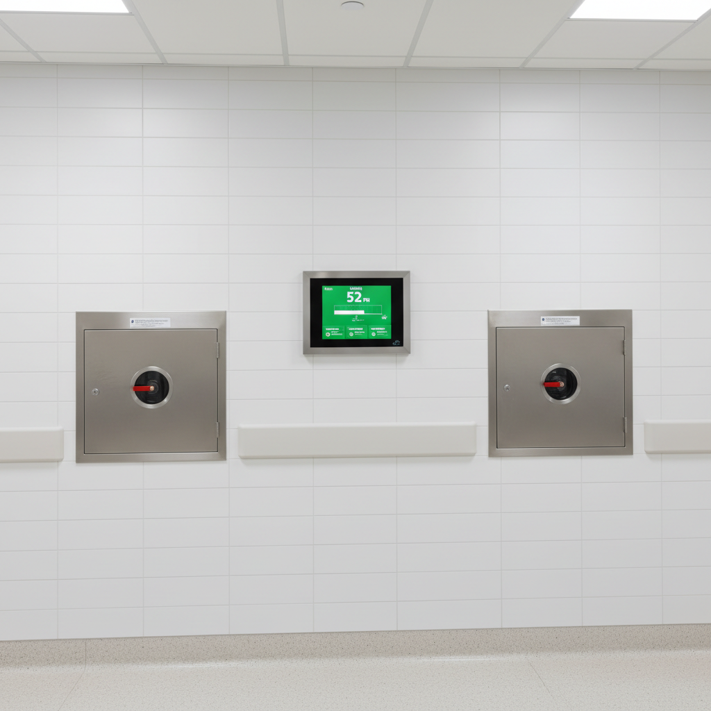
    Area alarm panels serve the clinical front lines. When placing and programming area alarms for medical oxygen, several human-factor and clinical requirements must be met. | Diagram text | |, | | [Gas Shutoff Valve] AREA ALARM PANEL | | v OXYGEN: 52 PSI | | [Pressure Sensor] =====> VACUUM: 18 inHg | | MED AIR: 50 PSI | | v | | (To Patient Terminals) [Mute] [Test] |

    Visual and Audible Requirements

    • Display: Modern area alarms display dynamic, digital pressure readings (psig for oxygen, nitrous oxide, and medical air; inHg for medical vacuum).
    • Alarm Setpoints: An audible tone (minimum 80 dBA at 10 feet) and flashing visual alarm must engage when oxygen pressure drifts ±20% from nominal setpoint:
      • High Alarm: ≥ 60–66 psig (depending on nominal calibration)
      • Low Alarm: ≤ 40–44 psig
    • Silence Capability: Staff must have access to a silence button that quiets the audible tone while keeping the visual LED/display flashing red until pressure is restored to safe clinical operating ranges. If a secondary alarm condition occurs on another gas (e.g., Medical Air drops) while the oxygen alarm is silenced, the panel must re-engage the audible sounder for the new condition.

    In specialized clinical rooms, specifically wet procedure locations where high concentrations of fluids and medical electrical devices interact, facility planners often coordinate gas panel installations alongside isolated power panels. For comprehensive safety standards regarding isolated power and line isolation monitors in surgical environments, refer to our definitive guide on line isolation monitor testing and service.


    6. Major Alarm Panel Brands: Engineering Comparison

    Hospital engineering departments typically standardize on one manufacturer across their campus to streamline preventative maintenance, board replacement, and clinical staff familiarity. Below is an engineering comparison of industry-standard medical gas alarm platforms available through Medical Testing Solutions.

    Manufacturer / Model SeriesNetwork ProtocolDisplay TypeTransducer InterfaceNotable Installation Considerations
    BeaconMedæs (TotalAlert Infinity)Ethernet, BACnet, Modbus, Web BrowserFull Color TouchscreenRemote or Integral (Digital Twisted Pair)High-resolution graphics; integrated web server allows remote viewing without specialized software.
    Amico (Alert-2 Series)Ethernet, BACnet IP, Modbus RTULCD & LED Digital DisplayMicroprocessor-based transducersHighly modular chassis; allows field expansion of additional gas modules without replacing the entire enclosure.
    Ohio Medical (Guardline Series)Modbus, Analog Contact ClosuresHigh-visibility LED DigitsLocal 4–20 mA or dry contactDurable, straightforward retrofit panel; preferred where legacy wiring architectures exist.
    Pattons Medical (Touch Panel Series)BACnet, TCP/IPInteractive LCD Color TouchDigital Transducer with auto-addressingEasy calibration via screen interface; quick firmware loading via USB.

    You can explore certified medical gas equipment, sensors, and replacement modules through our dedicated medical gas products catalog.


    7. ASSE 6030 Third-Party Verification and Commissioning

    A medical gas alarm panel installation is never complete simply because the contractor finishes wiring and turns on the power switch. NFPA 99 §5.1.12 dictates that prior to any patient use, the entire system must undergo formal verification performed by an independent, ASSE 6030-certified Medical Gas Systems Verifier. | Diagram text | |, | | COMMISSIONING VERIFICATION | | [ASSE 6010 Installer] - → [Installation Complete] - → [Pre-Testing Signed] | | v | | [ASSE 6030 Verifier] - → [Independent Verification] | | * Actuate every switch/transducer | | * Vent lines to verify ±20% trip points | | * De-energize primary power to verify EES transfer | | * Check fail-safe open-circuit response | | * Certify documentation and signage |

    The Verification Mandate

    The verifier must not be employed by the installation contractor. This separation ensures an objective, rigorous life safety audit. Medical Testing Solutions maintains a nationwide team of ASSE 6030 certified verifiers who carry calibrated testing instrumentation traceable to NIST standards.

    Verifier Checklist for Oxygen Alarm Panels

    During medical gas verification, the verifier performs 100% component testing:

    1. Actuation Calibration: Every pressure sensor is isolated and vented using a certified test gauge. The verifier records the exact pressure where the high-pressure and low-pressure alarms trip to confirm they fall precisely within the ±20% threshold.
    2. Audible Decibel Measurement: Sound output is measured at 10 feet using a calibrated sound level meter to guarantee audibility over ambient hospital background noise.
    3. Power Interruption & Fail-Safe Test: The panel's primary breaker is de-energized to validate correct transfer to emergency power. Signal wires are disconnected from transducer terminals to verify the panel initiates an immediate visual/audible system fault.
    4. Independent Annunciation Audit: Master Panel 1 and Master Panel 2 are tested simultaneously to ensure both units display identical warning states without signal degradation or cross-talk.
    5. Labeling and Identification: Gas name, operating pressure, and monitored zone must match architectural submittals and NFPA 99 color coding (Green for Oxygen in North America).

    Following successful testing, the verifier issues a formal certification document that must be archived permanently in the facility’s safety records for Joint Commission (TJC), CMS, or state health department audits. Following verification, facilities must maintain compliance through annual medical gas inspections to guarantee sensor drift does not compromise alarm thresholds over time.


    8. Troubleshooting Common Medical Gas Alarm Installation Deficiencies

    During hospital retrofits and annual compliance surveys, our engineers routinely encounter common field errors that violate code or lead to false nuisance alarms.

    Deficiency 1: Shared Neutral or Ground Loops

    Symptom: Digital pressure displays fluctuate erratically, or alarm panels trigger false low-pressure alarms intermittently.
    Cause: Signal wiring was pulled through conduits containing high-draw line-voltage machinery, or the transducer shield wire was grounded at both the sensor body and the alarm panel enclosure, creating an electrical ground loop.
    Remedy: Always ground the shield at one end only (typically the alarm back box) and isolate low-voltage transducer runs from power conductors.

    Deficiency 2: Sensors Installed on Supply Headers Without Isolation Ports

    Symptom: Technicians cannot service or replace a malfunctioning pressure transducer without shutting down the primary oxygen riser feeding patient care areas.
    Cause: The installing mechanical contractor omitted brass needle or quarter-turn shutoff valves at the sensor drop.
    Remedy: Retrofit an accessible, lockable quarter-turn isolation valve with a secondary test port.

    Deficiency 3: Misconfigured Baud Rates or Modbus Addressing

    Symptom: Area alarm displays "Communication Failure" or "Module Offline."
    Cause: Digital multi-gas panels share a single internal communication bus. If two gas modules (e.g., Oxygen and Medical Air) are assigned the same hex/DIP switch address, bus contention knocks the panel offline.
    Remedy: Verify addressing tables in the manufacturer manual and verify proper terminal termination resistors (typically 120-ohm resistors at the end of the RS-485 chain).

    If your facility is dealing with recurring nuisance alarms or legacy hardware failures, our technicians provide comprehensive medical gas maintenance services to recalibrate transducers and stabilize electrical instrumentation.


    9. Comprehensive Facility Alarm Inspection Checklist

    Ensure your clinical and facility operations adhere to national accreditation standards by referencing this quick-action checklist before requesting third-party sign-off:

    • Dual Master Surveillance: Panels are installed in two separate locations, with at least one staffed continuously (24/7).
    • Dedicated Power: Feeds originate from the emergency electrical system (EES) critical branch, with breaker lock-outs installed.
    • Sensor Placement: Area alarm sensors are tapped in strictly downstream of the corresponding zone valve box.
    • Liquid Bulk Inputs: Master panel monitors primary liquid level, secondary supply actuation, and reserve bank pressure.
    • Pressure Setpoints: Audible and visual cues actuate within ±20% of standard line pressure (40 psi low / 60 psi high).
    • Fail-Safe Integrity: Breaking signal loop triggers immediate audible fault warning.
    • Third-Party Sign-Off: System certified by an independent ASSE 6030 verifier with documentation archived on-site.

    Partner with Medical Testing Solutions for Turnkey Alarm Compliance

    Navigating NFPA 99 and ASSE compliance during a critical oxygen alarm installation leaves zero margin for error. Medical Testing Solutions delivers end-to-end expertise across the complete project lifecycle. We sell leading, code-compliant alarm platforms from industry manufacturers, deploy ASSE 6010 certified installers for precision mounting and wiring, and provide independent ASSE 6030 verification that guarantees your hospital passes accreditation inspections on day one.

    Whether you need to upgrade an outdated master alarm network, replace failing zone pressure transducers, or schedule your facility's mandatory annual testing, our engineering team is ready to assist.

    Headquarters:
    Medical Testing Solutions
    501 E Las Olas Blvd, Ste 300
    Fort Lauderdale, FL 33301

    Speak with an ASSE-Certified Medical Gas Specialist Today:
    Call us at (754) 315-1078 or request a quote online to review your architectural drawings and equipment submittals.


    Frequently Asked Questions

    NFPA 99 requires that all Category 1 health care facilities maintain two independent master alarm panels located in separate spaces (one in engineering, one under continuous 24/7 observation). Area alarm panels must be placed in all critical care units, anesthetizing locations, and nursing units supplied by localized zone valves, with sensors placed downstream of the zone shutoff. Panels must be wired to the facility's Essential Electrical System (EES) and verified by an independent ASSE 6030 professional prior to patient use.

    Master alarm panels must be placed in two distinct locations: one in the facility engineering or maintenance office and the second in a space monitored 24 hours a day, such as a main security station, telephone switchboard, or central communications room. Area alarm panels must be positioned inside or immediately adjacent to the clinical zone they serve (such as a centralized nurse station in an ICU or outside an operating room) at eye level where medical personnel can see and hear them instantly.

    No. NFPA 99 explicitly prohibits placing area alarm sensors upstream of the zone valve. The sensor must be installed on the patient side (downstream) of the shutoff valve. If a zone valve is manually closed during a room fire or pipe rupture, the downstream sensor must immediately detect the drop in oxygen pressure and sound the alarm at the nurse station.

    NFPA 99 mandates that hospital medical gas alarm panels be tested periodically as part of an ongoing equipment management plan. Typically, visual and audible indicators are function-tested monthly or quarterly, while full system verification—including isolating sensors, venting lines to confirm high/low trip points at ±20%, and testing backup power transfer—must be conducted at least annually by qualified personnel.

    Yes. NFPA 99 §5.1.10.11 requires that personnel installing medical gas piping, alarm panels, and source equipment hold valid credentials meeting the ASSE 6010 Professional Qualification Standard for Medical Gas Systems Installers. Furthermore, the installation cannot be placed into service until an independent, third-party ASSE 6030 verifier inspects and approves the installation.

    This article is provided for educational purposes and reflects industry standards as of publication. Always verify against current NFPA 99, CGA, and AHJ requirements. Medical Testing Solutions is ASSE-certified and ready to help — contact us for facility-specific guidance.

    Request a quote for your facility

    Talk with Medical Testing Solutions about your next inspection, repair or equipment request.

    Get a quote in 1 business day

    I agree to receive text messages from Medical Testing Solutions, L.L.C. at the phone number provided, including informational and marketing messages. Consent is not a condition of purchase. Message frequency varies. Message & data rates may apply. Reply STOP to opt out or HELP for help. See our Privacy Policy and Messaging Terms.

    Prefer to talk? Call (754) 315-1078

    Related articles