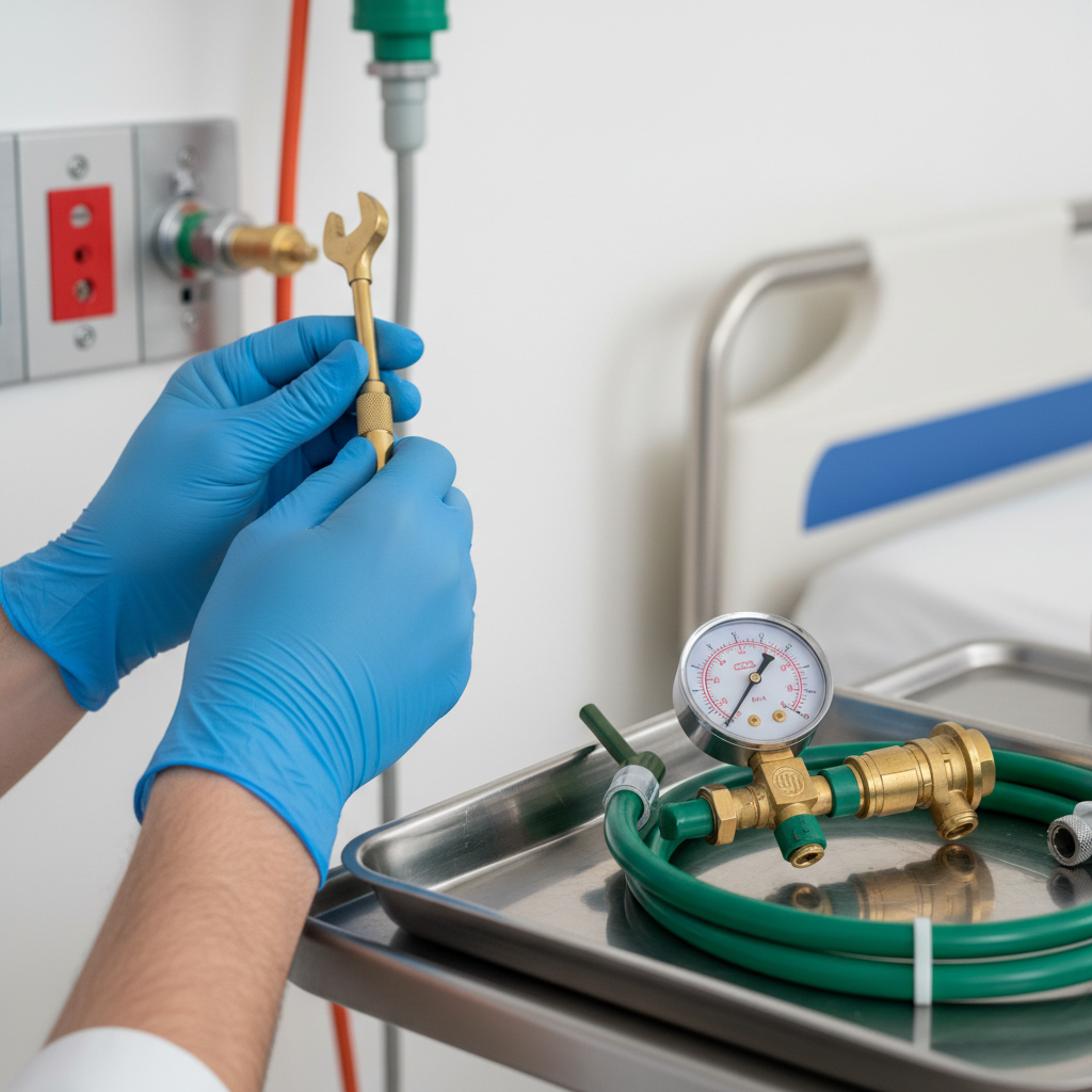
Oxygen Concentrator Wall Outlet Repair: NFPA 99 Compliance Guide
Medical gas pipeline terminal units, commonly called wall outlets or terminal stations, form the critical interface between bulk gas sources (including cryogenic liquid cylinders, high-pressure manifolds, and healthcare facility oxygen concentrator supply systems) and patient life-support equipment. When an oxygen wall station develops an audible hiss, fails to latch a flowmeter, or drops dynamic operating pressure, patient safety and code compliance are immediately compromised.
Executing oxygen concentrator wall outlet repair requires more than swapping parts. Because these terminal units distribute life-sustaining gas under 50 to 55 psig of pressure, repairs must align strictly with NFPA 99 (Health Care Facilities Code), ASSE Series 6000 standards, and Compressed Gas Association (CGA) guidelines.
In this comprehensive technical guide, clinical engineers, facility managers, and biomedical technicians will learn how to identify common outlet failure modes, troubleshoot gas-specific latching mechanisms, execute compliant barrel and primary valve rebuilds, and navigate mandatory ASSE 6030 verification requirements following system maintenance.
Understanding Terminal Units in Oxygen Concentrator Systems
In healthcare facilities equipped with an on-site Medical Air/Oxygen Generating System (such as molecular sieve Pressure Swing Adsorption [PSA] or Vacuum Pressure Swing Adsorption [VPSA] concentrators operating under NFPA 99 Chapter 5), oxygen is piped through ASTM B819 seamless medical-grade copper tubing to wall, ceiling, or boom-mounted terminal units.
An oxygen wall outlet consists of two primary operational sections:
- The Rough-In (Back Body): Permanently brazed to the secondary branch piping. It houses the secondary check valve (automatic shut-off mechanism), which stops the flow of gas when the front assembly is removed for servicing.
- The Finishing Assembly (Front Body / Latch Valve): Contains the primary check valve, the gas-specific indexing interface (such as Chemetron, Ohmeda/Diamond, Puritan Bennett, or DISS), internal O-rings, springs, and cosmetic faceplates. | Diagram text | |, | | WALL ROUGH-IN | | [ Branch Piping ] -> [ Secondary Check Valve ] -> [ Body ] | | (Sealed interface) | | FRONT FINISHING ASSEMBLY | | [ Primary Valve ] -> [ Gas-Specific Latching ] -> [ Face ] | When an oxygen concentrator delivers USP or 93 Percent Oxygen into this system, mechanical wear, particulate ingress, and elastomeric degradation inevitably compromise these mechanical joints. Routine servicing through professional medical gas maintenance services prevents unexpected clinical downtime and dangerous oxygen enrichment hazards.
Common Outlet Failure Modes and Diagnostic Protocols
Most terminal unit malfunctions fall into three categories: continuous gas leakage, mechanical latching failure, and flow/pressure restrictions.
1. Chronic Gas Leaking (Audible Hissing)
Oxygen leaks typically occur in one of two states:
- Uncoupled Leak: Gas escapes when no adapter, flowmeter, or regulator is plugged into the wall outlet. This indicates failure of the primary poppet seat, worn internal elastomeric O-rings, or a compromised secondary check valve within the rough-in assembly.
- Coupled Leak: Gas leaks only when an apparatus is connected. This points to a degraded front outer sealing O-ring, damaged quick-connect probe geometry, or a cracked latching sleeve.
2. Mechanical Latching and Retention Failures
Clinicians frequently report that flowmeters "pop out" or fail to lock into the wall receptacle. In quick-connect styles (such as Chemetron rectangular pins or Ohmeda cylindrical groove latches), mechanical latch pins or internal retention leaf springs wear down from repeated insertion cycles. If the latch plate fails to lock securely, line pressure (50–55 psig) will forcefully eject the connected equipment.
3. Cross-Connection and Keying Wear
NFPA 99 § 5.1.5.1 strictly mandates non-interchangeable, gas-specific connections. Over decades of heavy use, latching slots can deform. If the gas-specific mechanical keyway wears excessively, it introduces the life-threatening risk of accepting another medical gas adapter (such as Medical Air or Nitrous Oxide).
4. Pressure Drops and Dynamic Restriction
An outlet may display 50 psig static pressure on an uncoupled gauge but plummet below 40 psig once a high-flow therapy device is attached. This dynamic pressure drop is typically caused by desiccant dust or particulate buildup migrating from upstream equipment, particulate accumulation on the secondary check screen, or an incompletely seated secondary stem.
Why this matters for compliance: NFPA 99 § 5.1.14.2.3.1 requires medical gas outlets to deliver 100 normal liters per minute (NLPM) at a minimum dynamic residual pressure of 45 psig. A degraded wall outlet that drops below this threshold during emergency ventilation violates federal accreditation standards and jeopardizes patient safety.
Quick-Connect vs. DISS: Structural Comparison
Modern facilities utilize either Diameter Index Safety System (DISS) threaded connections or proprietary Quick-Connect configurations. Diagnosing and repairing these outlets requires matching exact replacement parts to the specific make and model.
| Outlet Standard | Primary Latching Mechanism | Common Failure Points | Rebuild Complexity | Common Clinical Setting |
|---|---|---|---|---|
| DISS (CGA V-5) | Threaded collar (9/16"-18 UNEF gas-specific threads) | Thread stripping, face gasket hardening, damaged poppet tip | Low (mostly gasket and cartridge replacement) | Critical Care, Operating Rooms, NICU |
| Ohmeda / Diamond | Dual-pin / spring-loaded collar with circular barrel | Retention ring fatigue, worn inner Viton O-rings, sleeve sticking | Moderate (specialized poppet removal tool needed) | General Med-Surg, Emergency Dept |
| Chemetron | Rectangular latch mechanism with dual indexing notches | Broken latch spring, worn latch fingers, release button jamming | Moderate (latch block and spring plate replacement) | General Inpatient, Procedure Rooms |
| Puritan Bennett | Non-interchangeable mechanical geometry with plunger release | Plunger spring failure, barrel galling, dry seal blowout | Moderate to High (multi-stage disassembly) | Legacy Facilities, Ambulatory Surgical Centers |
| Schrader | Twist-and-lock keyed pin connection | Alignment pin shear, collar track wear, inner core failure | High (limited modern parts availability) | Legacy Systems, Industrial & Specialty Clinics |
When servicing or modernizing outdated terminal units, facilities often choose retrofitting to standardized designs during scheduled medical gas installation projects to simplify their biomedical spare-parts inventory.
Step-by-Step: Repairing an Oxygen Concentrator Wall Outlet
Only personnel qualified under ASSE Series 6000 standards, specifically ASSE 6010 Installers, ASSE 6030 Verifiers, or ASSE 6040 Maintenance Technicians, should perform internal work on medical gas distribution hardware. | Diagram text | |, | | STEP 1: ISOLATE GAS ZONE | | Close Zone Valve Box & depressurize station | | STEP 2: DISASSEMBLE FRONT BODY | | Remove faceplate, trim plate, and latch assembly | | STEP 3: EXTRACT POPPET & INSPECT SEALS | | Inspect secondary check, replace barrel seals/poppets | | STEP 4: REASSEMBLE WITH CLEAN COMPONENTS | | Torque to spec; verify no hydrocarbon contamination | | STEP 5: POST-REPAIR VERIFICATION | | Cross-connection, static/dynamic leak, flow testing |
Required Tools and Medical-Grade Materials
- Clean, degreased hand tools (brass or lint-free cleaned stainless steel)
- Manufacturer-specific rebuild kit (OEM poppet, primary spring, secondary check assembly, outer retaining ring)
- Oxygen-compatible lubricant (Christo-Lube® MCG 111 or Krytox® GPL-205; never use hydrocarbon-based grease or WD-40)
- Calibrated medical gas pressure test gauge assembly (0–100 psig) with certified flow orifice (100 NLPM)
- Gas-specific purge probe and certified calibrated electronic leak detector or approved non-hydrocarbon leak testing solution (Snoop® Medical Gas grade)
Step 1: Isolate the Local Zone Valve Box (ZVB)
- Notify nursing and clinical leadership that gas service to the target zone will be temporarily interrupted. Ensure no patients depend on that oxygen pipeline branch; deploy back-up E-cylinders with verified regulators.
- Locate the designated Zone Valve Box serving the room.
- Close the zone valve fully and verify pressure drop using a dedicated test gauge plugged into an unserviced station downstream.
Note on Secondary Check Valves: While modern rough-ins incorporate automatic secondary check valves that seal when the front cartridge is withdrawn, NFPA 99 cautions against relying on secondary checks for complete pipeline isolation during extensive rebuilds. Debris can prevent the secondary check from seating fully, creating a continuous 55 psig oxygen discharge directly into the technician's face. Isolate at the zone valve whenever feasible.
Step 2: Remove Trim Plates and Front Latch Assembly
- Remove the aesthetic wall plate screws and pull the trim cover away from the wall.
- Unscrew the sub-plate fasteners holding the latch mechanism to the rough-in back body.
- Carefully slide the latch mechanism out. On Chemetron styles, release the retaining clips; on Ohmeda/Diamond units, unscrew the barrel assembly counter-clockwise using the proper spanner wrench.
Step 3: Inspect and Rebuild the Primary Barrel Assembly
- Extract the primary poppet assembly, inner spring, and seal package.
- Inspect the secondary check valve located inside the rough-in body. Ensure the secondary poppet seat is unpitted and its return spring has adequate tension.
- Clean the rough-in interior using lint-free, oil-free medical gas wipes.
- Replace the internal O-rings, secondary seat washer, primary poppet, and spring using the dedicated OEM repair kit.
- Apply an ultra-thin film of oxygen-safe fluorinated lubricant (such as Christo-Lube) strictly to dynamic O-rings. Avoid excessive lubrication; surplus lubricant attracts airborne dust and desiccant fines.
Step 4: Reassembly and Mechanical Alignment
- Re-insert the rebuilt cartridge/poppet assembly into the rough-in.
- Fasten the latch body, ensuring the indexing pins or keying alignment slots match the medical gas service (Oxygen Green plate / CGA index).
- Secure all mounting hardware to the manufacturer's specified torque (typically 12–18 in-lbs for sub-plate screws). Do not overtighten, as this can warp plastic latch sleeves and cause binding.
Step 5: Post-Repair Testing and Functional Verification
Do not return the outlet to clinical service until you have completed full testing. Re-open the Zone Valve Box slowly, allowing pressure to equalize, and proceed to the mandatory verification protocols detailed below.